Snap Sorter Guide
SnapSorter Setup & Operating Guide
Thank you for purchasing the Reloading Automation SnapSorter. This device is designed to automatically sort similar-diameter reloadable brass cases into separate containers based on case height.
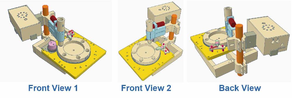
System Overview
The SnapSorter system consists of two primary components:
Base Unit – Mounts to a table or ¾" EMT conduit
Sorter Head (Base Sorter Unit) – Contains the motor, wheel, proximity sensor, and output paths
A parts list is provided at the end of this guide.
Mounting Options
Table Mount (Recommended for High Volume)
Mounting to a table provides maximum stability. When using a sufficiently large brass collator, multiple SnapSorters can be mounted 16–24 inches apart, allowing:
Two or more units to sort the same caliber
Feeding into the same output containers
Example:
Two units sorting 9mm can process over 100 lbs of brass per hour, depending on collator speed.
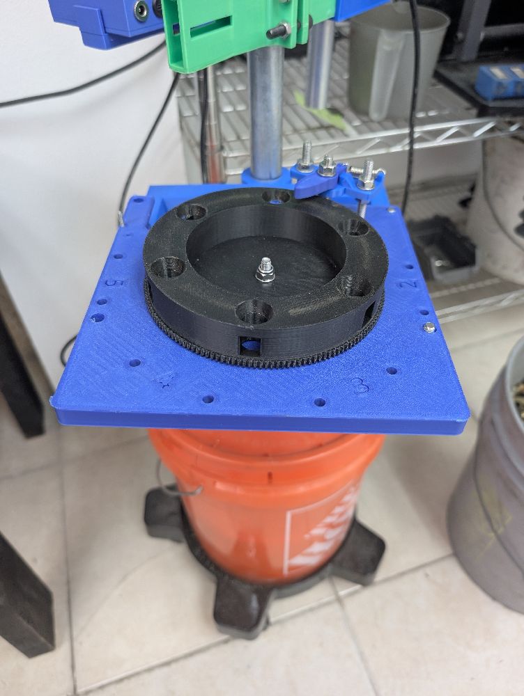
EMT Conduit Mount (Portable Option)
Alternatively, the SnapSorter can be mounted using ¾" EMT conduit:
Insert EMT into a 5-gallon bucket
Fill bucket halfway with concrete
Allow concrete to cure
Place bucket on a rolling cart if desired
This setup allows the unit to be easily relocated as needed.
Before You Begin
After receiving your SnapSorter:
Inspect all components for shipping damage.
If anything is damaged, contact us immediately so replacements can be sent.
- Although the Height Arms were adjusted correctly, you may need to adjust them slightly due to your brass not being SAMMI specs or shipping may have moved the Arms slightly.
- This unit is not meant for totally hands off use. It will jam on occassion due to bad/defective brass and using the wrong caliber brass (i.e. 40 S&W dropping into a 9mm or a 32 ACP into 9mm). Ensure that once a brass jam occurs, immeditelty turn off the machine and clear the jam.
⚠️ Important:
Many components are 3D-printed. Do not overtighten fasteners, as this may cause breakage. Damage caused by overtightening is not covered under warranty.
Safety
Do not wear rings, bracelets, or loose items that may snag moving components
Always turn power OFF before clearing jams or making adjustments
Assembly & Setup
Step 1 – Mount the Base Unit
Secure the Base Unit to:
Your table, or
The ¾" EMT conduit
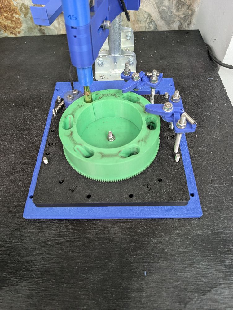
Refer to Figure 1 for correct mounting orientation.
Step 2 – Install the Sorter Head
Place the Sorter Head onto the Base Unit.
Nuts may be installed, but are not required
We typically leave ours unsecured
Step 3 – Install Motor Assembly
If not already installed:
Slide the motor base into the Sorter Head
Attach the spring between the motor plate and the Head
Step 4 – Install Output Tubes (Not Included)
Install case output tubes into the Sorter Head:
¾" OD / 5⁄8" ID tubing
PVC or clear vinyl tubing
10' lengths commonly available at Home Depot
We recommend clear vinyl tubing.
Ensure tubing reaches the collection bucket with extra slack to allow for bucket movement.
Step 5 – Final Assembly
If the Sorter Head was removed during setup:
Reinstall it onto the Base Unit
Step 6 – Adjust Caliber Feed Tubes
There are two adjustments for the Caliber Feed Tubes.
- Adjust the height of the feed tube (DTWC). This is measured from the top (flat) side of the Caliber wheel to the bottom side of teh Caliber Drop Tube. Each sorter size will have a different setting. Note, the Drop Tube size is indicated by Small (S), Medium (M) or Large (L) on the side for the tube.
- 9mm = 12mm DTWC (S Drop Tube)
- 40 S&W = 13mm DTWC (M Drop Tube)
- 38 Special = 14mm DTWC (M Drop Tube)
- 44 Special = (L Drop Tube)
- 45 ACP/GAP = (L Drop Tube)
- 223 / 300 Blackout = 18 DTWC (S Drop Tube)
- 308 = 27mm DTWC (L Drop Tube)
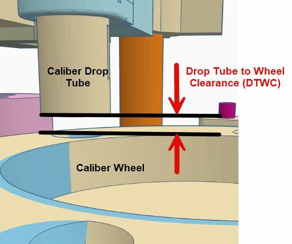
- Looking down adjust the center of the Caliber Drop Tube to be over the top of the drop hole in the Caliber Wheel.
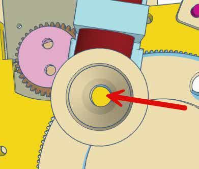
When adjusting the Drop Tube, you will find there will be a 'Sweet Spot' that will work best for your setup.
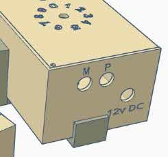
Electrical Connections
Connect the motor power wire to the “M” jack on the Control Box
Plug the Proximity Sensor into the “P” jack
Plug the 12V DC power supply into the “12V DC” jack
⚠️ Important:
The “M” and “12V DC” jacks use the same connector type.
Ensure the power supply is NOT plugged into the “M” jack.
Double-check all connections before applying power.
Power-On Test
Plug in the 12V DC power supply
Press the Power button on the Control Box
You should observe:
Power button changes color
Proximity sensor LED turns red (no case present)
Wheel remains stopped
Sensor Test
Insert a small metal object (e.g., needle-nose pliers) into the Drop Tube
Sensor light should turn off
Wheel should begin turning continuously
Adjust the speed dial to increase or decrease wheel speed.
💡 Note:
The speed dial includes an OFF position that stops the motor while leaving the sensor powered.
General Operating Guidelines
Brass must be same diameter and similar height
Example: 9mm Luger, .380 ACP, 9mm Mak
Typical height range example:
.380 ACP ≈ 17mm
.38 Super ≈ 23mm
⚠️ Excessive height differences may cause:
Cases falling out
Wheel jams
Cases may be dirty or clean.
Clearing Jams
If a jam occurs:
Turn OFF the SnapSorter and brass collator
Push the Clutch back, away from the spring and Base Sorter Unit
This disengages the motor from the wheel
Rotate the wheel manually to clear the obstruction
If necessary, realign the Drop Tube
⚠️ Important:
Leaving the unit powered during a jam may damage the motor or other components.
Common Issues & Solutions
1. Case Did Not Drop into Output Tube
Release motor and rotate wheel slightly
Check for full output tube (under the Base Unit) backing into the wheel
Empty bucket and clear tubing
2. Cases Not Entering the Wheel
A. No cases detected
Ensure brass is feeding into the Caliber Feed Tube
Red sensor light indicates no cases present
With cases present, the light should be off
B. Feed tube blockage
Check for debris (grass, dirt, corncob, paper)
Check for incorrect caliber blocking the tube
3. Wheel Not Turning
A. Jam at Drop Tube
Clear jam and verify correct tube height
B. Nested cases
Remove nested case from wheel or drop tube
4. Cases Falling Out of Drop Tube
Ensure proper Drop Tube alignment
Reduce gap between Drop Tube and Wheel
Reduce speed for large rifle cases
⚠️ Large cases (e.g., .308, .30-06) rely on gravity.
Excessive speed may prevent full seating and cause jams.
Maintenance
Weekly:
- Check all screws and tighten as needed
- Clean machine, use a small amount of compressed air to blow off dust, dirt and corncob
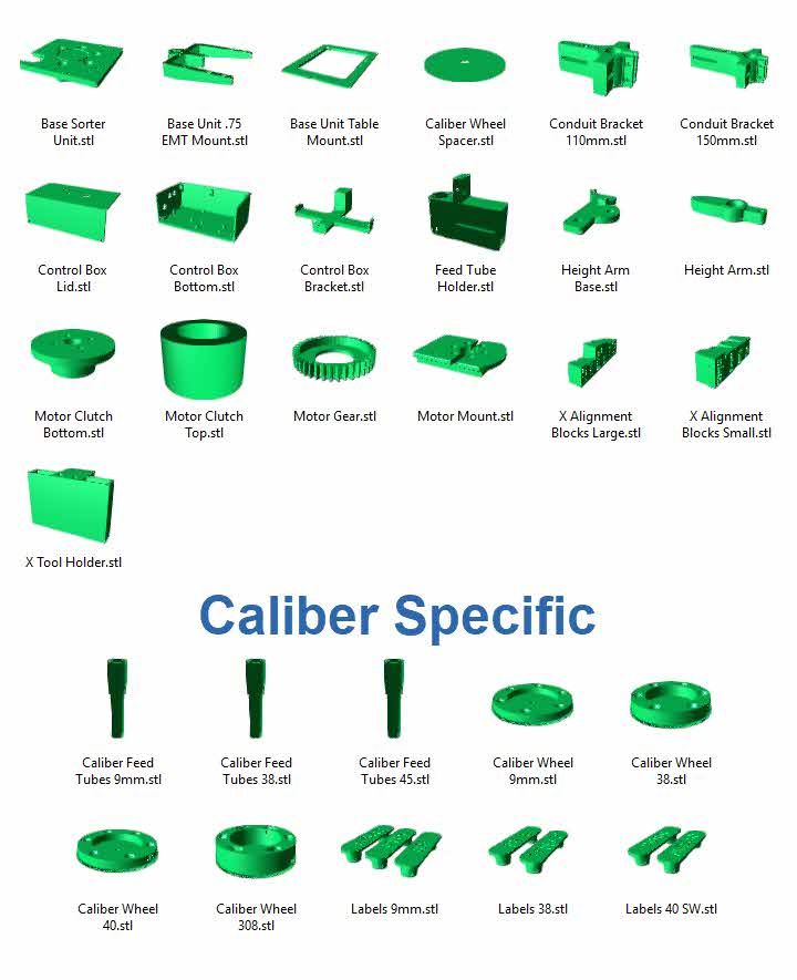
Parts Display